
Introduction to buried cable cover and NEC Table 300.5
Use this calculator to find the minimum cover — the depth of earth or concrete between finished grade and the top of the cable or conduit — for underground runs such as residential branch circuits, feeders to outbuildings, landscape lighting, and fiber. The lookup mirrors the actual structure of NEC Article 300.5 / Table 300.5: the required depth is a function of two things at once, the wiring method (direct burial cable, rigid metal conduit, or a listed nonmetallic raceway) and the location (open ground, under a slab, under a dwelling driveway, under a street, under a building, and so on). Special circuit types — residential 120 V GFCI-protected branch circuits and circuits of 30 V or less — get their own shallower columns.
Burial depth is not just a convenience detail. Too shallow can lead to damaged conductors, shock hazards, outages, and failed inspections. Too deep can increase cost, complicate drainage, and make future repairs harder. This page focuses on practical, code-aware planning, but it is not a substitute for your local inspector, utility standards, or engineered plans; the final word always belongs to the authority having jurisdiction and, where wiring is involved, a licensed electrician.
The calculator is most useful before you rent a trencher: deciding between direct burial cable and conduit, spotting where a driveway or street crossing changes the requirement, sizing the spoil pile, and documenting assumptions for the inspection conversation.
What “minimum cover” means (and what it does not)
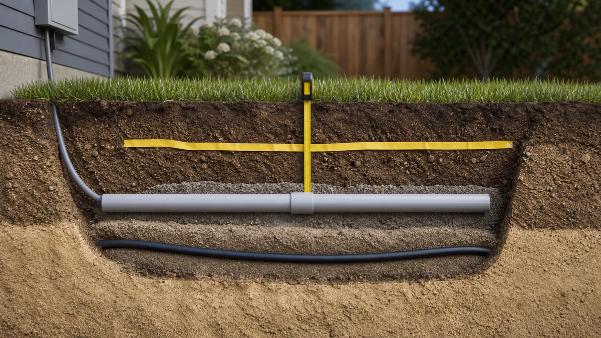
In the NEC, the depth requirement is expressed as minimum cover: the shortest distance between the top surface of the buried wiring method and the top surface of finished grade, concrete, or similar cover. For conduit, measure to the top of the conduit; for direct burial cable, to the top of the cable. A sand bed, warning tape, or backfill choice does not by itself reduce the required cover — only the specific table entries and notes do (for example, the “in trench below 2 in. of concrete” row, or the solid-rock note that allows a raceway under 2 inches of concrete).
Depth is only one part of a safe underground installation. You also need correct conductor sizing, wet-location ratings (THWN-2 in conduit, UF-B or USE-2 for direct burial), proper fittings, expansion and settlement allowances (the NEC requires provision for earth movement — an “S loop” of slack is common practice), and mechanical protection where the run emerges from grade, which Article 300.5(D) requires up to 8 feet above finished grade. Many failures happen at these transitions, not at depth.
How to use this burial depth calculator
- Pick a scenario preset if one matches your project (backyard receptacle, hot tub feeder, detached garage, landscape lighting, fiber run, street crossing), or leave it on “Custom”.
- Select the circuit type. Residential 120/240 V branch circuits, commercial circuits up to 1000 V, circuits over 1000 V, landscape/irrigation circuits of 30 V or less, and fiber each map to different columns or tables.
- Select the wiring method: direct burial cable, rigid or intermediate metal conduit (RMC/IMC), listed nonmetallic raceway such as PVC, EMT, or liquidtight flexible conduit.
- Choose the location. This is the row of Table 300.5 — note that a one- or two-family dwelling driveway is a different (shallower) row than a street, alley, or commercial parking lot.
- Enter voltage, overcurrent protection, and GFCI status so the calculator can test the residential reduced-cover column and the 30 V column honestly.
- Describe the dig: soil type, local frost line, run length, trench width, cable or conduit outside diameter, and sand bedding thickness.
- Click Calculate Required Burial Depth. Review the minimum cover, the method comparison for your location, the excavation estimate, the cross-section diagram, and every warning before you dig.
Formula and lookup logic: cover table, exceptions, and trench volume
The core of the calculator is a two-dimensional lookup that reproduces the shape of Table 300.5: pick the row from the location, pick the column from the wiring method, then allow a qualifying special circuit to use its shallower column. The code note behind that last step matters: where a wiring method from columns 1–3 is used for one of the special circuit types in columns 4–5, the shallower depth is permitted — which is why the residential GFCI exception can also reduce a PVC run from 18 inches to 12 inches, not just direct burial cable.
Plain-text condition rule: the reduced 12-inch cover column applies only when the circuit is a residential branch circuit, 120 V or less, GFCI protected, with overcurrent protection of 20 A or less. It is not applied to 240 V circuits, to commercial occupancies, or under streets and commercial driveways, where 24 inches applies to every method. When the conditions do not match, the calculator falls back to the ordinary wiring-method column and says so.
Once the cover requirement is known, the dig itself is geometry. The total trench depth adds the cable or conduit outside diameter and any sand bedding beneath it:
where cmin is the required cover in inches, dOD is the outside diameter of the cable or conduit, and dbed is the bedding thickness. The excavation volume in cubic yards for a run of length L feet and trench width w inches is:
The spoil pile is larger than the hole: excavated soil bulks up, so the calculator also reports the loosened volume using a typical 25% swell factor. Frost is handled as a floor, not an adder — when you flag a frozen or permafrost region, the minimum cover becomes the larger of the code value and your local frost line entry.
Simplified NEC Table 300.5 reference (circuits of 1000 V or less)
The table below summarizes the five columns and seven rows of Table 300.5. All values are inches of cover. Always consult the adopted code edition and local amendments for your exact installation; some cells carry conditions that a summary cannot fully capture.
| Location of wiring method | Direct burial cable | RMC / IMC | Listed nonmetallic raceway (e.g., PVC) | Residential 120 V GFCI ≤20 A | ≤30 V (UF or identified) |
|---|---|---|---|---|---|
| All locations not specified below | 24" | 6" | 18" | 12" | 6" |
| In trench below 2" of concrete | 18" | 6" | 12" | 6" | 6" |
| Under a building | 0" (in raceway, or MC/MI identified for burial) | 0" | 0" | 0" (in raceway) | 0" (in raceway) |
| Under ≥4" exterior concrete slab, no vehicles | 18" | 4" | 4" | 6" / 4" in raceway | 6" / 4" in raceway |
| Streets, highways, roads, alleys, driveways, parking lots | 24" | 24" | 24" | 24" | 24" |
| One- and two-family dwelling driveways and parking (dwelling use only) | 18" | 18" | 18" | 12" | 18" |
| In or under airport runways and adjacent restricted areas | 18" | 18" | 18" | 18" | 18" |
Key notes attached to the real table: cover is measured to the top of the wiring method; where solid rock prevents the listed depth, install a raceway and cover it with at least 2 inches of concrete extending down to rock; lesser depths are permitted where conductors rise for terminations or splices; and a special circuit (columns 4–5) run in a column 1–3 wiring method may use the shallower value. Circuits over 1000 V use Table 300.50 instead — 30 inches for direct burial in ordinary locations — and utility-owned lines follow the NESC and the utility's own standards, which are usually deeper still. The old “over 600 V” threshold is outdated language: the NEC moved the boundary to 1000 V in the 2014 edition.
Worked example: a backyard receptacle with a driveway crossing
Scenario: A homeowner is installing a receptacle on a post in the backyard for holiday lighting and a small pond pump. The circuit is 120 V on a 20 A GFCI breaker, and the route crosses the home's own driveway on the way. The homeowner is deciding between direct-burial UF-B cable and PVC conduit.
Option A (direct burial across the lawn): Choose circuit type Residential branch circuit, wiring method Direct burial cable, location Lawn / garden, GFCI Yes, 120 V and 20 A. The circuit qualifies for the residential column, so the calculator returns 12 inches minimum instead of the ordinary 24 inches — a real saving in digging effort. The cable must still be UF-B or another type rated for burial, with gentle bends and riser protection where it comes up the post.
Option B (the dwelling driveway crossing): Switch the location to One-/two-family dwelling driveway. This is the detail most summaries get wrong: a dwelling's own driveway is a separate, shallower row of Table 300.5 than a street or commercial lot. The qualifying GFCI circuit stays at 12 inches even under the dwelling driveway; without the GFCI qualification the direct-burial figure would be 18 inches. If this were a street, alley, or commercial parking lot, every wiring method — including rigid metal conduit — requires 24 inches, and conduit buys protection but no depth reduction.
Option C (PVC conduit): Choose wiring method Nonmetallic raceway (PVC). The ordinary lawn figure is 18 inches, but because the circuit qualifies for the residential column, the shallower 12 inches is still permitted. The trench math then shows the full dig: 12 inches of cover + 1.9 inches of conduit OD + 3 inches of sand bedding ≈ a 17-inch-deep trench. At 50 feet long and 8 inches wide that is about 1.7 cubic yards of excavation — call it 2.2 cubic yards of loose spoil once the soil bulks up.
Practical tips for a safer, easier install
The depth number is only one decision. The items below reduce damage risk, improve serviceability, and make inspections smoother.
- Call 811 before you dig and hand-dig near marked utilities. Utility locates reduce the chance of striking gas, water, telecom, or electric lines.
- Use the right cable: NM-B (“Romex”) is not for direct burial. Use UF-B or USE-2 for direct burial, or wet-rated conductors such as THWN-2 in an approved conduit.
- Protect the transitions: Article 300.5(D) requires protection for direct-buried conductors from the required depth up to 8 feet above finished grade — conduit risers, bushings, and proper fittings.
- Consider conduit at crossings (driveways and paths) even where depth alone would pass. A sleeve makes future replacement a pull instead of a dig.
- Install warning tape about 12 inches above the run. It is required above certain service conductors and cheap insurance everywhere else.
- Leave slack for earth movement: Article 300.5(J) requires allowance for settlement and frost; an S-loop at each end is common practice (roughly 6 inches per 25 feet).
- Backfill carefully: Article 300.5(F) prohibits rocks, sharp objects, and corrosive material against the wiring; screened fill or sand around the run prevents insulation damage.
- Inspect before backfill: many jurisdictions require an underground rough inspection prior to covering. Photograph the open trench with a tape measure in frame.
- Document the route: record measurements from permanent landmarks. Future repairs are faster when you know the path.
Limitations, assumptions, and what the inspector actually decides
This is an educational planning model of NEC Article 300.5 / Table 300.5 concepts (with Table 300.50 planning values for circuits over 1000 V), not the adopted code text of your jurisdiction. It assumes the special-circuit columns require qualifying cable or raceway types, models fiber from typical industry practice rather than the electrical table, and treats frost as a simple floor on depth. It does not model concrete encasement credits beyond the listed rows, occupancy-specific rules, utility (NESC) requirements, or engineered duct banks. Verify the result with the authority having jurisdiction, the serving utility, local amendments, and a licensed electrician before excavation — the most reliable “correct depth” is the one your inspector accepts for your specific installation.
Underground burial depth: frequently asked questions
How deep should I bury electrical wire under a lawn or garden?
In areas without vehicle traffic, NEC Table 300.5 lists 24 inches of cover for direct burial cable, 18 inches for PVC or another listed nonmetallic conduit, and 6 inches for rigid or intermediate metal conduit. A qualifying residential 120 V, GFCI-protected, 20 A branch circuit may be reduced to 12 inches. Local amendments can be stricter, so confirm with your inspector.
Does conduit always mean you can bury cable shallower?
Only in some locations. In lawns and gardens, rigid metal conduit can sit at 6 inches of cover and PVC at 18 inches, versus 24 inches for direct burial cable. Under streets, roads, alleys, and commercial driveways, however, Table 300.5 requires 24 inches of cover for every wiring method, so conduit still provides mechanical protection there but no depth reduction.
What if solid rock prevents reaching the required burial depth?
NEC Table 300.5 has a specific note for this case: where solid rock prevents full-depth burial, the wiring must be installed in a metal raceway or a nonmetallic raceway permitted for direct burial, and the raceway must be covered by at least 2 inches of concrete extending down to the rock. Confirm the detail with the authority having jurisdiction before you pour.
Is fiber optic burial depth governed like electrical cable?
No. Fiber and communications cable are usually governed by provider standards, right-of-way rules, and local permitting rather than NEC Table 300.5, which covers electrical power circuits. Typical industry practice is 12 to 18 inches for residential drops, 24 to 36 inches for distribution runs, and 36 to 48 inches under road crossings, but the network owner's standard controls.
How deep do low-voltage landscape lighting wires need to be buried?
Circuits limited to 30 volts or less and wired with Type UF or another identified cable qualify for the shallowest column in Table 300.5: 6 inches of cover in ordinary locations, and 18 inches under one- and two-family dwelling driveways. Many installers still go deeper so a shovel, edger, or aerator cannot reach the cable.
Do I need warning tape above a buried electrical line?
The NEC requires a warning ribbon at least 12 inches above underground service conductors that are not encased in concrete and are buried 18 inches or more below grade. For ordinary branch circuits and feeders it is recommended practice rather than a universal code requirement, but many utilities and local codes do require it, so plan on installing it.
Safety and compliance reminder
Underground wiring can be dangerous. De-energize circuits before working, use proper PPE, and follow permit and inspection requirements. If you are unsure about conductor sizing, bonding and grounding, or wet-location ratings, consult a licensed electrician. Where this page and your inspector disagree, the inspector wins.
Status messages will appear here.
Arcade Mini-Game: Trench Check Calibration Run
Use this quick arcade run to build trench-day instincts: catch the practices inspectors want to see and dodge the shortcuts that fail inspections or damage cable.
Start the game, then use your pointer or arrow keys to catch useful inputs and avoid bad assumptions.